Designing and Assembling Control Panels
April 27, 2022
By Chris Kregoski, Product Engineer, AutomationDirect
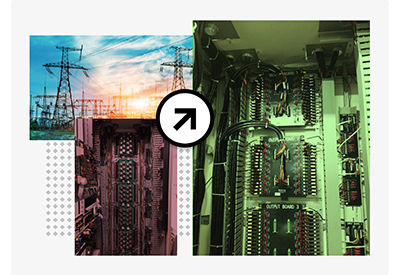
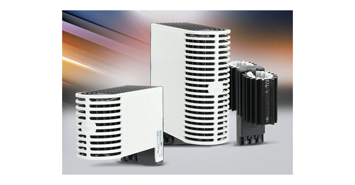
Industrial control panels are needed to support the electrical, instrumentation, and control (EIC) aspects of any modern machine or process. Today’s digitally-controlled systems include an increasing number of smart devices and field sensors, and there is an accelerating need to communicate this edge-sourced data up to supervisory systems and the cloud. Therefore, the demand for control panels to house EIC components at the edge is also growing (Figure 1).
Understanding the basics of designing, assembling, and testing control panels is important for original equipment manufacturers (OEMs) and systems integrators (SIs), and for the end users who will receive these panels and operate them for years or decades. Panel design is a specialty, and it requires much more than picking some parts and bolting them into an enclosure, but there are many products and resources to help get the job done.
This article walks through some of the components and processes involved with creating a typical industrial control panel.
Understanding requirements
Some projects are highly specified by design engineers, with extensive stipulations for makes/models of parts, a process functional description, and more. All designs are subject to various electrical, UL, and safety codes, requirements, and regulations. A detailed exploration of these aspects is beyond the scope of this article, but exploring an example of creating a control panel for a flying cutoff machine will help illustrate many of these points.
Flying cutoff machines are used on many types of production lines for plastic strand extrusion and other on-the-fly material cutoff needs where a continuous stock of material is produced and must be cut to the desired size. To avoid interrupting the continuous production, the cutoff blades are arranged to travel at the same speed as the moving product, while cutting across the product.
While some EIC components can be installed in the field without a control panel, it is much more common to put these devices in control panels. Industrial control panels serve many purposes:
- – Protecting interior-mounted components from exterior environmental conditions of heat, cold, moisture, contaminants, and mechanical abuse.
- – Guarding workers from coming into contact with the components and electricity.
- – Distributing, converting, and providing circuit protection for electrical and communications.
- – Centralizing EIC devices like programmable logic controllers (PLCs), input/output (I/O) devices, human-machine interfaces (HMIs), motor controls like variable frequency drives (VFDs), networking devices, instrumentation, and much more.
A basic block diagram is the easiest way to graphically depict major components and their relationships, even before component makes/models are selected. In this example, a PLC elsewhere will interface with I/O in this remote control panel so that a motion controller can be commanded to drive four servos as needed. Because of the nature of this equipment, a safety controller is needed to monitor various sensors and stop equipment operation if any hazardous situation is detected. Various power distribution and wiring provisions will also be required.
Documenting with drawings
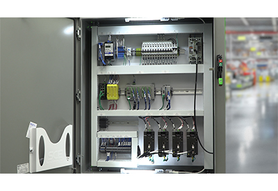
While a block diagram is often the very first step when designing a control panel, a comprehensive drawing package is needed to properly document any design. Detailed drawings are used so purchasing can order parts, a shop can fabricate the control panel, technicians can install it, and users can work with it (Figure 2).

A typical drawing package should include some or all the following drawings:
- – Cover page and drawing list.
- – Bill of materials (BOM), a detailed list of makes/models/quantities indicating usage.
- – Schedule of nameplates and tags.
- – Cable and/or wire lists (optional, but helpful especially for cut-to-length cables).
- – Interior layouts with dimensions and wire management provisions.
- – Main power distribution drawings including incoming power, 3-lines for 3-phase AC power, all circuit breaker and fuse overcurrent protection, transformers, DC power supplies, and grounding provisions.
- – Block diagram or system architecture, showing PLC/HMI, data, and networking, with pertinent device addresses and communication settings.
- – I/O module and field termination strip drawings.
- – Intelligent device drawings for VFDs, motion controllers, servos, safety controllers, instruments, and the like.
Engineering and design personnel will need to consider many more details as they create these drawings, such as:
- – Power consumption.
- – Overcurrent protection and conductor sizing.
- – Conductor/cable routing and tagging schemes.
- – UL requirements.
- – Code compliance.
A good drawing package proves that requirements are met, and describes all necessary mechanical, electrical, instrumentation, controls, pneumatic, and motor control details sufficiently.
Diving into details
Control panel design is typically an iterative process, with changes made as more details become known. Products are selected to meet the need, and once these are mostly known the designer must create a layout, size the enclosure, and perform many other design steps.
Enclosures
Enclosures are available in many sizes and materials of construction. Painted steel is the standard choice and is economical. However, control panels used for washdown or wet areas are often specified as stainless steel or fiberglass. Advanced designs are available for usage in sanitary areas typically found in food, beverage, and pharmaceutical plants.
Layouts
In particular, enclosure sizing involves compromise as the interior must be large enough to easily house all components, but the exterior must be compact enough to fit within constrained areas. The design of the exterior of the enclosure must be detailed to show where user interface devices like pushbuttons and HMIs are located. The subpanel needs to be laid out for easy assembly, while providing enough working space for future expansion. Wiring paths must keep low-voltage instrument and communication cables away from higher voltage power, while safety circuits should be segregated from other circuits. Some devices require minimum spacing around them for cooling, and conduit/cable entry/exit locations must be defined.
Thermal management
Most components generate some heat, and all have minimum and maximum operating temperature specifications. Control panels mounted outdoors, in the sun, or with large heat-generating components like VFDs will need fans or air conditioning units. Panels installed in humid or cool areas may need heating provisions to maintain a minimum temperature and reduce harmful condensation. These heating and cooling devices drive up power requirements and may increase the enclosure size.
Schematics
Schematics are the drawings used to define how components are wired together. There is not one right way to organize schematics, conductor/cable numbering, and component labelling, but some localities or end users may require a particular style or method. IEC and NFPA styles communicate the same information in slightly different ways, and a hybrid approach is possible. For example, one approach is to group sheets by function, and assign wire numbers by voltage, page, and line. Point-to-point connections are described by the schematics, showing where every conductor lands. Before schematics can be finalized, it is important to choose the make/model every device and the labelling of each connection.
Assembly follow-through
Once the drawings are approved, parts are ordered, and materials are received, the panel shop can begin assembly. Note that even though control panels are assembled in a controlled shop location, all workers should still wear safety glasses, gloves, and any other necessary personal protective equipment (PPE). Careful alignment, precise angles, and cleanliness will pay off later in the build, and will improve the final appearance for a professional look.
The first step is marking the interior panel—sometimes called a backplane or subpanel—and exterior layouts to match the drawings using a T-square and a mechanical pencil and blue tape. Pencil marks and blue tape are easily removed later in the process. Before drilling any holes, workers will usually mock the parts into place to ensure clearances look proper. This also gives them the chance to mark where mounting holes for components and wired ducts should be drilled.
Once designers and assembly personnel are confident in the layout, the components are removed, and a center punch establishes where each hole is needed. Mounting hardware size varies, but it is common to use 8-32 screws for DIN rail and wire duct. Fabricators will drill pilot holes, then finish with a combination drill-tap bit in the desired size, while protecting their tools and work piece with cutting oil, then debur all holes on both the front and back of the panel (Figure 3). For the enclosure exterior, the fabricator may have specialty tools like hydraulic punches to make pushbutton, instrument, or cable gland openings.

At this point, parts can be populated onto the panel. This includes wiring ducts (which themselves must be cut to fit), DIN rail, and other devices. The DIN rail can then be populated with end blocks, terminal blocks, and other devices. Terminal blocks should be installed together tightly. Factory jumpers/bridges are preferred over hand-made jumpers to save installation time and improve performance.
With all components installed, wiring can begin (Figure 4). Usually, this proceeds from the largest power conductors down to the smaller signal cables, but any order is acceptable. Depending on the device type, it may be possible to land a bare wire. However, many users prefer a crimped lug or ferrule to be installed prior to termination. Each screwed connection should be torqued properly. Labels are applied to devices, terminal blocks, and cables. It is best to label components on the subpanel so the device can be removed and replaced in the future without affecting the tag.

Grounding and bonding are particularly important and deserve special attention. Every device, and usually most signal cable shields, should be grounded per the drawings. Note that larger power devices require larger ground conductors, so wire sizes should be indicated on the drawings. For grounding connections to the subpanel or enclosure, paint needs to be removed to ensure a good connection. A bonding brush attached to a drill is ideal to reliably perform this step.
Testing
Once assembly is completed, the shop should test their work and provide documentation of:
- – Parts verification.
- – Overcurrent device ratings.
- – Overall layout/arrangement.
- – Proper wire/component tagging.
- – Grounding/bonding.
- – Point-to-point wiring tests.
In most cases it is possible to progressively power-up components, check basic circuits, and confirm I/O signals. For more advanced systems with PLCs, HMIs, VFDs, and more, technicians should be able to load in the configurations and programs and demonstrate communications. While full functional testing is usually only possible on self-contained OEM equipment, there is often a great amount of simulation that can be performed to confirm the control panel is functioning properly.
Good control panel basics ensure best results
An industrial control panel slapped together from assorted parts and pieces is likely to be problematic. Because functional control panels are so important, and becoming more so due to digitalization and IIoT efforts, designers and users are best served by researching available parts and helpful resources on the subject.
They can then proceed in an orderly manner to design, procure, fabricate, and test these control panels, with confidence that the panel will perform reliably and withstand the elements. Understanding good control panel basics is crucial for those performing the detailed work, and it also benefits those from other disciplines who need to work around and with control panels.
About the Author

Chris Kregoski is a product engineer at AutomationDirect in Cumming, GA., on the Productivity PLC development and support team. He spent nearly a decade as the owner of Woodwest Controls, a small system integrator, servicing start-ups in malting, brewing, distilling, and water treatment industries.
![]()
https://www.automationdirect.com/adc/home/home